11.1 PRINCIPAL SPACE ENGINE APPLICATIONS
By definition, space engines supply all those forms of rocket propulsion which a spacecraft requires for various maneuvers in space. This may include attitude control and stabilization, coplanar and interplanar orbit changes, trajectory corrections, rendezvous maneuvers, lunar and planetary landings and takeoffs, and retrofiring (reversed thrust for deceleration) during reentry into the Earth's atmosphere. The thrust of a space engine may be a fraction of a pound or many thousands of pounds. Besides a few solid propellant systems (used mainly for single-start, retrofiring rockets) and stored gas systems (used only in applications for thrust levels less than 1 pound, and for a total impulse of less than , the great majority of the space engines are of the liquid propellant type. Because of their inherent operational advantages, liquid systems most likely will continue to dominate the space engine field, even when advanced nuclear and electrical propulsion systems become available.
Liquid propellant space engine systems may be divided into two basic groups: vehicle main propulsion systems and reaction control systems. These differ not only in function and thrust level but also in the type of propellant they use, the degree of required controllability and thrust variation, and system components. Common to virtually all of them is the requirement that they be able to start and operate reliably in the cold vacuum conditions of space.
Spacecraft Main Propulsion Systems
The main propulsion systems for most spacecraft are pressure-feed, storable hypergolic propellant systems, such as the A-4 stage propulsion system, with thrust levels up to about 25000 pounds. These systems include propellant tanks and their pressurization system, control valves, main thrust chamber assembly or assemblies, and a gimbal mechanism or some other type of thrust vector control. Most main thrust chambers are ablatively cooled, while attached nozzle extension skirts are radiation cooled.
In a few cases, turbopump-feed systems have been used, such as the 50000 -pound thrust (sea level) turbopump-feed liquid oxygen/ammonia rocket engine produced by the Reaction Motors Division of the Thiokol Corp. for the North American X-15 research plane. As space missions become more ambitious, requiring increased total impulse and higher-energy cryogenic propellants, turbopump-feed systems will undoubtedly play an increasingly important role in spacecraft propulsion. Most space missions require multiple starts and a certain degree of thrust throttling. These requirements usually account for the principal differences between the main propulsion systems for spacecraft and those for booster vehicles.
Reaction Control System
These systems deviate more drastically from other liquid propellant rockets, because of their design arrangement and their thrust levels, which run from 1 pound up to 500 pounds, with most systems probably falling within the 1 - to 100 pound range. The thrusts of these systems may be used to provide attitude control to properly position a spacecraft, to aline a spacecraft for a midcourse corrective or terminal maneuver, and to stabilize the vehicle after separation from another stage or during Earth reentry.
As a rule, attitude-control engines are used in opposing pairs to produce pure couples about an axis. They are mounted in clusters to simplify plumbing and wiring. Parallel pairs of engines, or individual units, are used for translational movements along the vehicle axis, as in rendezvous and docking maneuvers.
The reaction control engine systems are usually pressure fed, using monopropellants or storable hypergolic propellants. In all cases thrust level and duration must be very closely controllable. The thrust chambers may be ablatively cooled or radiation cooled, depending on the application.
Application Example
The application of various space engine systems may best be illustrated by typical examples, such as the spacecraft for the U.S. Apollo Moon-landing program. The space vehicle system to carry the Apollo aloft, the Saturn V, consists of the S-1C (five F-1 LO RP-1 enginestotal thrust, 7500000 pounds), the S-II (five J-2 engines-total thrust, 1.15 million pounds), and the S-IVB (one J-2 LO2 engine-thrust 230000 pounds) stages (fig. 11-1). The Apollo spacecraft itself consists of the command, the service, and the lunar excursion modules.
The service module has a 21900 -pound, fixedthrust restartable pressure feed (UDMH) engine as its main propulsion system. Its thrust chamber has a nozzle expansion area ratio of 60 to 1 and is gimbaled for thrust vector control by a redundant electromechanical device. This engine system provides the thrust for midcourse correction as well as for entry into, and escape from, lunar orbit. It also serves as an abort system, if necessary, after the launch escape system has been jettisoned.
The service module's reaction control system is composed of four separate and interconnected pressure-feed engine systems utilizing the same propellants as the main propulsion system. The systems are mounted external to the forward skin of the service module at intervals. Each engine system consists of four pulse-modulated, 100 -pound thrust chamber assemblies with a 40-to-1 nozzle expansion area ratio. These provide the three-axis attitude control for the spacecraft during Earth orbit, lunar injection, lunar orbit, LEM docking and separation from the command module.
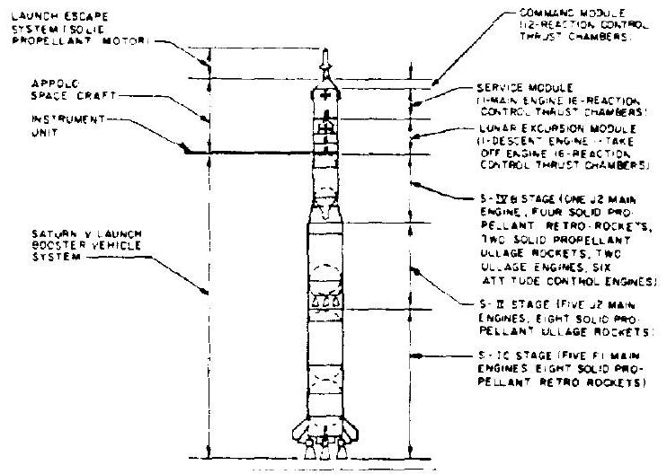 Figure 11-1.-The propulsion systems of the Saturn for the . S. manned Apollo flight to the Moon program.
The command module requires thrust only for three-axis attitude control during reentry into the Earth's atmosphere and to assist the service module's reaction control system during separation of the two modules. The command module reaction control system is made up of two separate, interconnected pressure feed engine systems, either of which is capable of completing the Earth reentry mission. These engine systems are located in the aft equipment compartments. Each system consists of six pulse-modulated, 91-pound, thrust, chamber assemblies of a 9-to-1 nozzle expansion area ratio.
The lunar excursion module (LEM) has two main engine systems, one for the descent to the Moon's surface, and the other for takeoff from the Moon and injection into lunar orbit for rendezvous with the command and service modules. The LEM descent engine system has a nominal thrust level of about 10500 pounds, which can be gimbaled and throttled over a range. The takeoff engine is a rigidly mounted, 3500 -pound, fixed-thrust engine, which doubles as an abort engine in the early portion of the mission. The LEM also carries an attitude control system which uses 16 thrust-chamber assemblies. All are pressure fed, using a (UDMH) propellant combination.